Two-Phase Flow in Vertical Tubes
- cvbarcarse
- Sep 10, 2021
- 3 min read
August 31 - September 13, 2021 // Transport Laboratory I
Primary Objectives
To visually observe the motion of a single slug and investigate experimentally the relation between the slug velocity and slug dimension.
To investigate experimentally the relation between gas flow rate and the gas volume fraction (void fraction) for the slug flow regime in two phase gas/liquid flow in a vertical tube.
What is a "two-phase flow"?
A two-phase flow or a liquid flow is significant in a variety of chemical engineering applications such as the simultaneous transport of the gas and oil in horizontal pipelines or a vertical wells several flow regimes can occur, depending on many factors, including the orientation of the pipe the individual magnitudes of the liquid and gas flow rates and physical properties such as density, surface tension, and viscosity.
For vertical pipes (the situation here), there are four principal flow regimes and
which occur successively at ever increasing gas flow rates.
Bubble flow in which the gas is dispersed as small bubbles throughout the liquid which is the continuous phase.
Slug flow in which the individual small bubbles have started to coalesce together in the form of slugs. The liquid phase is still continuous.
Annular flow in which the fast moving gas stream is now a continuous phase that encompasses the central portion of the tube with the liquid forming a relatively thin film on the tube well.
Mist flow in which the velocity of the continuous gas phase is so high that it reaches as far as the tube wall and entrains the liquid in the form of droplets.
In the experiment, we investigated the slug flow regime for the flow of air and solutions in the tube. In this regime, surface tension and viscosity are possibly relatively unimportant, especially in the tube of larger diameter: also, the liquid density plays only a small role in determining the shape of the slugs, but is important if pressure-drop calculations are needed.
Materials
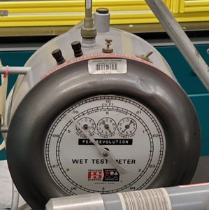
Wet Test Meter
Hose
Airflow Supply Valve
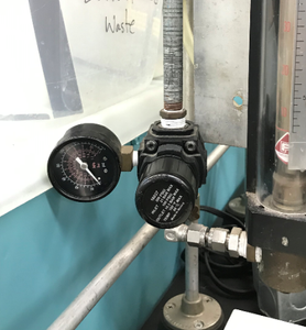
Rotameter
Tube Connector
Air Flow Tube
Timer/Stopwatch
Graduated Cylinder
Vertical Tube (mounted on an apparatus)
Apparatus
I. Calibration

II. Single Slug Flow

III. Continuous Slug Flow

Procedures & Contributions
I was in charge of ensuring that the rotameter is calibrated by levelling the wet test meter using the foot screws to make sure that the bubble is in the center of the test meter eye. Next, I connected the wet test meter connection tube behind the rotameter and unlocked the inlet valve to begin the air supply to the rotameter. In our case, a pressure of 35.0 psi was too high since one of the air flow tubes connected to the back of the rotameter disconnected--so we opted out for a pressure of 20 psi instead. I locked the knob of the rotameter shortly after. Lastly, I set the ball position to 10, recorded the various ball positions in increasing increments of 10 and recorded the wet test meter rotational time until the rotation on the device came to a stop. After, the collected numbers were converted in relation to one complete revolution to cubic feet.


Once the calibration was complete, a procedure was carried out for a Single Slug Flow where solutions of water, confectioners sugar, and vinegar were collected in distinct measurements and put in the vertical tube with 600 mL of water. Here, I made sure to practice turning the knob of the rotameter to make sure the slugs were precise and measurable. Once I had enough practice, we recorded a total of 30 trials for each solution. For the Continuous Slug Flow, I needed to turn the knob frequently instead of turning it once. This section was measured about 20 times for each substance. For each trial, I called out the height of each slug’s ball position.


Applications
The general situation in which the gas (air) and liquid (water) are traveling upwards together at individual volumetric flow rates G and L respectively, in a tube of internal diameter D. In general, there will be an upward liquid velocity ULm across a plane A-A just ahead of the gas slug. By applying continuity and considering the gas to be incompressible over short distances, the total upward volumetric flow rate of liquid across A-A must be the combined gas and liquid flow rates entering at the bottom, namely G+L. The mean liquid velocity at A-A is therefore ULm = (G + L)/A, where A is the cross-sectional area of the tube.
References
CHE3221L TRANSPORT LABORATORY I two phase flow(1) [DOCX]. (2021, June 5). California Polytechnic University, Pomona.
Two phase flow Procedures [DOCX]. (2021, June 5). California Polytechnic University, Pomona.
Comments